There were the wrong acrylate components we made in last two laser cutting. Some of the components cannot be putted on the arm, some of the holes we designed were too small. Also, because we over turned the servos manually, we crashed three servos in this way...... R.I.P.
This was the second try of laser cutting after we modified the plan of robotic arm. The video was a short video recording of real time laser cutting for anyone who was interested to see about laser cutter. By the way, it was very smelly while the cutter was running even exhaust fans was turning-on together. The mist was toxic mostly since it was the sublimate of materials. After the first try of laser cutting, we were testing the acrylate components and modifying the set-up of the robotic arm. In this short video, our group leader Leoson would explain the difference between forward kinematics (FK) and inverse kinematics (IK) through his understanding. The technical essay that he read can be found in REFERENCE. This was a simple test of the hardware we bought in October. This design of casing components was done in Adobe Illustrator. The file could input to the university's laser cutter to make some fine cutting parts as this image. 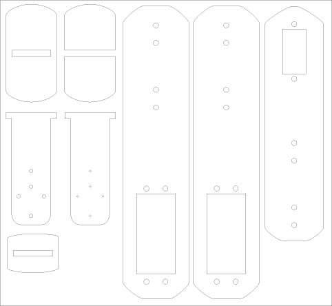 The first model of robotic arm we designed through the 3D animation program - Maya. This animation is very useful to visualize the plan of hardware. SM4703 - Robotic Art Project First Proposal Till Death Do Us Part  Artist Statement: Pen and paper, knife and fork, key and lock... Just like a couple, relationships exist in tools. They work closely together to maximize their value. But what if they are too close? Desk and Chair, an inseparable pair. Please take a seat. Materials: Arduino uno x 2 Motor x 4/8 Wheels x 16 Screws 3-5mm plastic sheet (Laser cut) Chair x 1 Table x 1 Drafts: Construction Plan: Basically, we would install the motors and the rollers/wheels on the legs of the table and the chair. By using laser cut machine/drill, we could design the position of holes on their legs for installing the necessary tools. Arduino is using to locate the table and chair. It would be placed under the boards of table and chair. For the ultra-sonic sensors, we still need time to test which position is the best way to detect. Once we have decision about the sensors position, we will attach them on the surfaces of the table and the chair, and bridge them using wires. Technical Difficulties: 1. Need to calculate the force and voltages. 2. Need to design how to install the rollers/wheels. There are many difficulties in this project. For example, we need to calculate the force according to the weight of materials (table/chair). We need to design the structures of bases for wheels and motors in order to attach them to the legs of the table and the chair. In this case, we have to learn how to use the laser cutter and how to draw the structures. Due to the limit budget, we can’t purchase some powerful and expensive motors, which can drive the average weight of human. Thus, the final product is not able to be seated by a human. Otherwise the rollers under the legs will be broken. Today a website to introduce an amazing robot was just born! - Isaac
| 
AuthorIsaac Chan was a group member in this project who managed this website. He was a student of New Media in City University of Hong Kong and would graduate in 2015. This is his first time to produce the documentation of artwork seriously. ArchivesCategories |


 RSS Feed